I got a new (to me) Thinkpad recently, and thought I should document the process of upgrading the LCD screen. Years ago this sort of thing was very easy to find on forums and the like, but useful information is held ephemerally in Discords and obtusely in YouTube videos, so let's use some good ol' HTML and strike a blow for freedom of information or whatever.
The conclusion is that I got this 2240x1600 IPS panel working great in the laptop. Below you can read about the process and what parts I used.
I finally moved on from my 51nb Thinkpad X2100 in favor of a Thinkpad P14s (Gen 4), with a nice snappy AMD Ryzen 7 mobile processor in it. While the 3:2 display from my previous laptop will be missed, ever since the third generation of the Thinkpad T14/P14 lineage, a desirable feature has been (re)introduced: 16:10 aspect displays are finally showing up! I'm not fond of 16:9 on the computer, be it for creative work, programming, or even writing like this. The return to 16:10 is not unique to the Thinkpad, but can be seen across many laptops within the last few years.
My model is a Thinkpad P14s, but it's worth noting that the T14, T14s, P14, and P14s are all closely linked. Specifically, the T14s is the lighest and thinnest of the bunch, while the base T14 and P14s share the same physical chassis. The P14 is a little chunkier, and is the most powerful. Processing power, if you want to imagine it in a linear fashion, roughly scales with the amount of chonk in the computer. The P14s I chose sits in the middle, a pinch above a regular T14, and more than adequate for my needs.
At the time of writing, there exist fifth and sixth generation iterations of this laptop. The reason I aimed for the fourth generation is (beyond cost) the fact that there isn't an unsightly bump protruding from the top for the sake of a fancier camera. That, and there isn't a tacky button on the keyboard for a Windows feature I do not want and will neber use. This article isn't about that, so we'll move on from this topic.
This generation of hardware came with a few options. I bought this computer in lightly used condition, so I was not in a position to customize the machine's configuration. From Lenovo's spec sheet, I was able to gather that the machine would be equipped with one of the following screen options:
Note: I'm so relieved we've moved on to IPS being standard even among the cheapest options. Personally, a VA panel would make me happy as I've really enjoyed those for static (text) and pictures before, but anything is better than the TN panels of yesteryear. It used to be that IBM would sell you IPS options on the high-end T60 laptops, branded as "Flexview", but that was certainly not the standard you could expect on used machines in following years.
What's interesting is, on the P14s Gen 4 Intel spec sheet, there's one more LCD that is absent from the AMD one, which is a 2240x1400 panel. What an unusual resolution, but not bad at all.
I have a lot of experience with WUXGA (1920x1200). While my desktop monitor is a big and tall 4K 3840x2560 IPS monitor, I'm generally happier at 100% DPI scaling and on a 14.0" screen 1920x1200 is completely adequate. As I described above, even the low-end configuration described above is such an improvement over the TN panels I've put up with in the past, so I was prepared to give a good old college try to whatever laptop should fall into the top of my lap.
But...
I was not prepared for what a "low-end" IPS panel looks like. The machine arrived, and while the panel worked, the color reproduction was just terrible! A little sleuthing tells me it covers 45% of the NTSC gamut. For reference, 72% NTSC is close to 100% sRGB, and is kind of a baseline to expect these days. I've used DSTN LCDs that were more colorful than this! I just didn't know they even bothered to make such a crummy LCD, but I guess the tradition of business-grade trash panels will never die.
To add insult to injury, the panel was a touchscreen model. I don't need or want that...
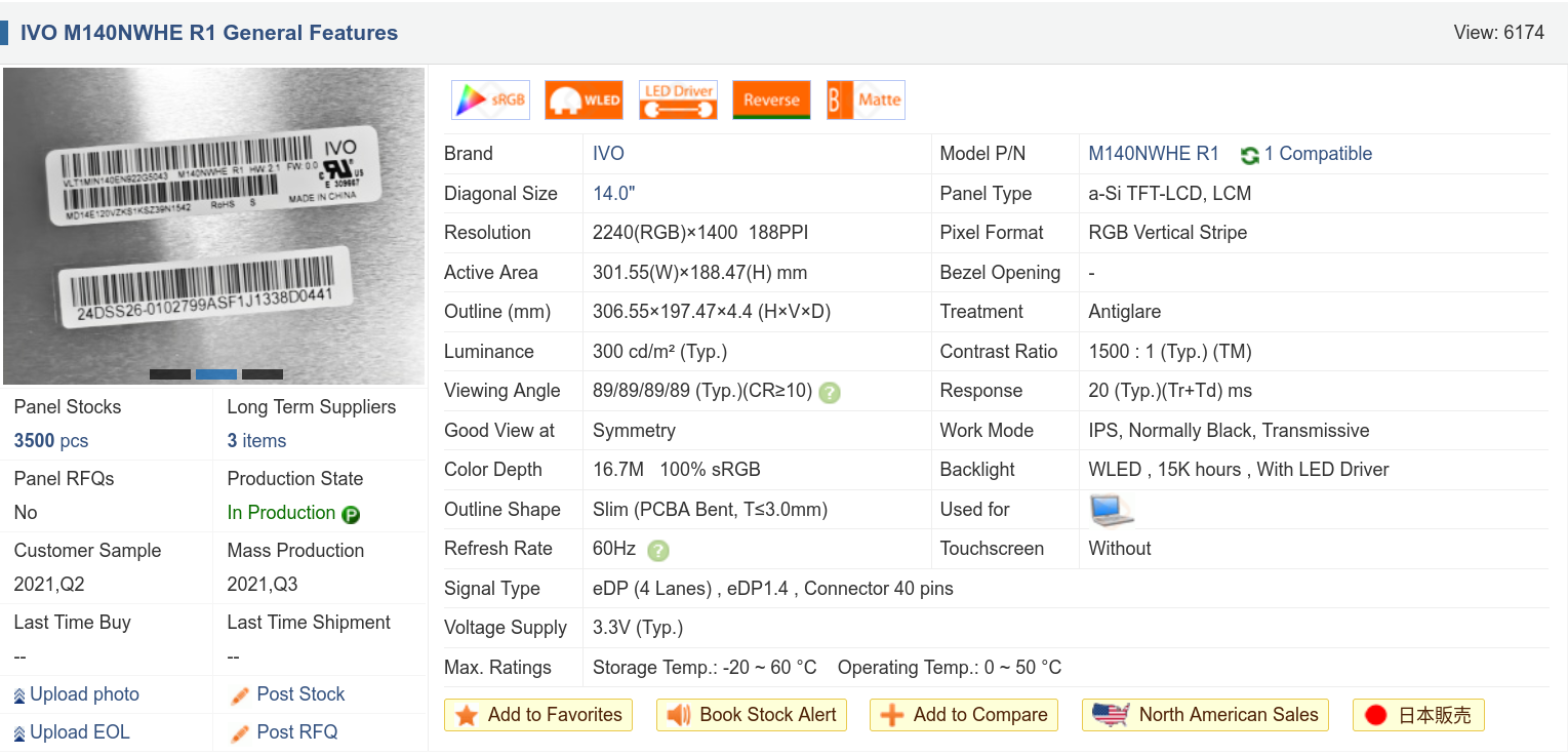
While i'm not thrilled to feel compelled to replace parts in a "new" laptop, I can accept it - it was cheap, and so are parts. A little research led me to find that others have been surprised by the poor color of this display and landed on the same decision, and also pointed towards a few LCD models that might work as a replacement. One that really stood out to me is that 2240x1400 panel from the Intel variant. The model number is M140NWHE R1, and I found a listing for a "Compatible Replacement" on Jeff Bezos' Used Book Website. For the price it was worth a shot, about $75 FreedomBucks. While it's not listed in the AMD spec list, it seems like it should obviously work if swapped on, and I liked the specifications.
I've been through this rodeo before, or so I thought, so I thought I should first research what kind of LCD connector my laptop already has. I know that modern laptop displays are usually eDP, and while the connectors seem to be a de-facto standard it is possible that the number of lanes used differs to accomodate higher resolution displays.
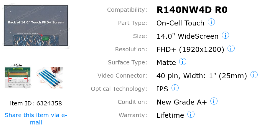
By inspecting my panel's EDID with ddcui, I found that the LCD model number is R140NW4D. Some listings on screen websites showed me that this panel has a 40-pin connector. This screenshot is from "laptopscreen.com" as an example, but I'm not here to make endorsements one way or another.
From some user comments and the hardware manual, I found that there's a 30-pin LCD connector for the two-lane eDP panels at 1920x1200, while other panels use a 40-pin connector featuring four lanes.
The new LCD's listing at Panelook.com indicated it also features a 40-pin connector.
At this point I thought I was good to go, so I patiently waited for my new panel to arrive.
Apologies: I didn't take much in the way of pictures for this process as I simply had my hands full. If I come across any suitable images or find an old photo I forgot about, I will update this section.
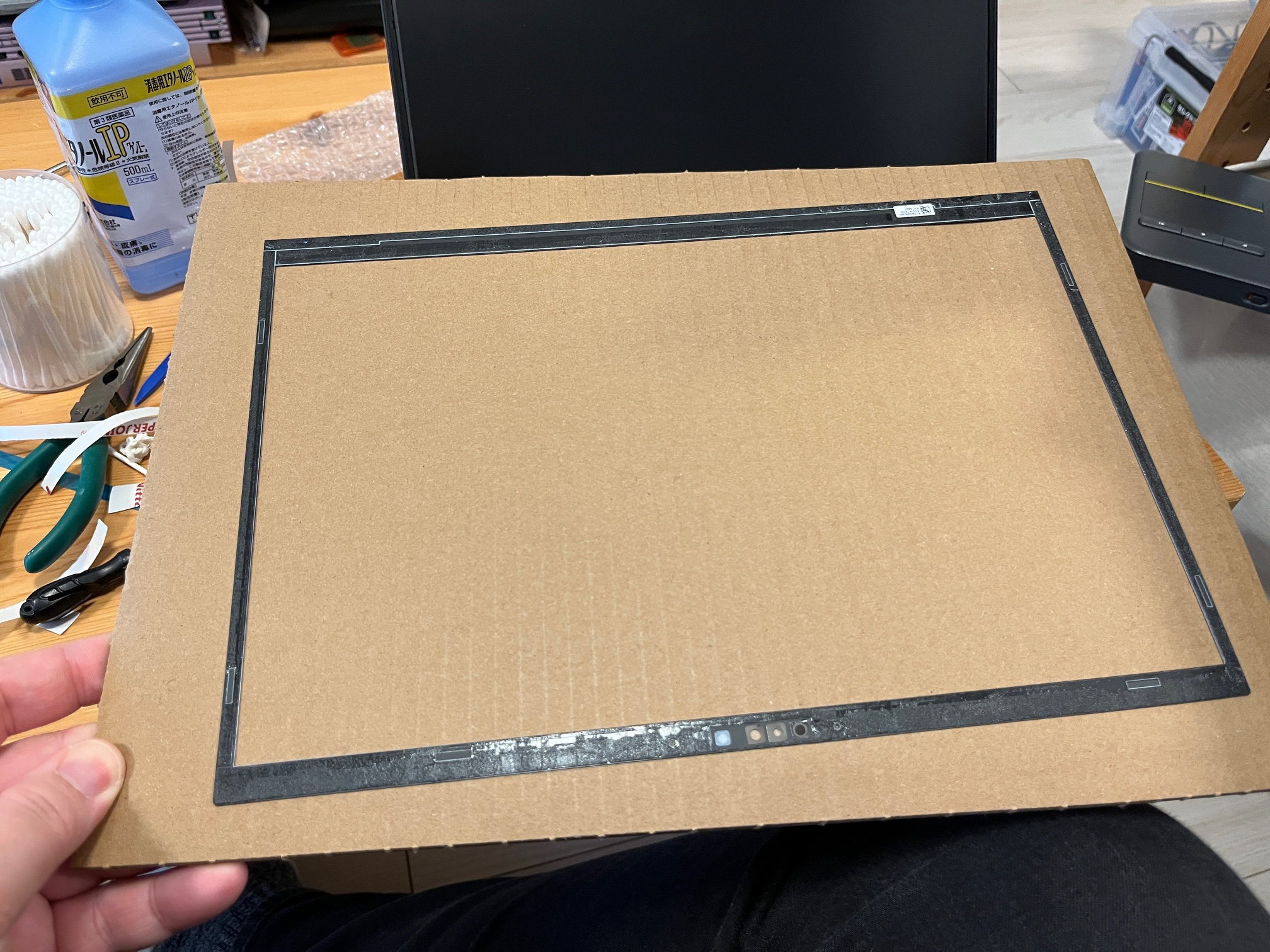
The new panel arrived, so I started to take the display assembly apart. You can follow the instructions to a T, but you'll notice that the screen bezel is called a sticker. It's not held on with screws, but is instead adhered to the edge of the LCD and to a sub-bezel that's snapped in around the edge! You're meant to just get a new bezel/sticker and install it alongside a new panel, but I wanted to give re-using the bezel a shot, so I very carefully removed it with a soft plastic tool going around the edge.
Getting purchase on the bezel was hard at first, but I was able to gain entry by starting in the lower-left corner. Making sure not to crease it in any spots I gently wedged in my plastic spudger tool while gently pulling up on the freed section. I went around the whole screen counter-clockwise this way until I had the bezel off cleanly, and then I carefully placed it upside-down on top of some cardboard to save until the process is done.
Next is this sub-bezel plastic frame. This goes around the edge of the LCD and is what makes contact with the palmrest when the laptop is closed. This is held in with a bunch of tough snaps, but with some gentle prying upwards from a corner and going around the edge I got it out without controversey. Actually, the bottom is a little tricky while the lid is still installed on the laptop, but opening it up at 90 degrees made it a lot easier.
Next is the LCD itself. It's another situation where there are no visible screws, so... it must be taped or glued in. Spoiler: I ruined the original LCD panel thoroughly for a lack of knowledge! Don't make the same mistakes I did! I went around the edge with the spudger and found that the LCD is held in with two vertical strips of double-sided tape on either side. I gently prised the panel up by getting the spudger underneath, fighting the adhesive. The correct operation would have been to notice and grasp the release tabs on the adhesive strips, and use that to evacuate the adhesive without straining the LCD.
The old panel came out, with a very obvious crack. I was not too bent out of shape about it because, frankly, that panel looked terrible.
The new panel arrived, and... just from comparing the two, it was obvious to me that this wasn't going to work. The old connector was certainly a 40-pin one, but visibly the LCD only employed two lanes for the eDP signaling, and some other wires were likely there for the touchscreen communications. While I could have plugged it in and tried it, who knows if I'd have blown a fuse for the backlight supply or something.
At this point I stopped and concluded I needed to look into the LCD connections more thoroughly. In fact, there are at least two 40-pin connectors, one featuring two lanes + touch on a 40-pin connector, and another with four lanes on the same connector pinned in an incompatible fashion. Hackaday features a page describing some common eDP laptop panel pinouts, and it would have been great to have looked at it before getting this far! Oh well, time to order a cable.
The necessary cable's model number is DC02C00U410, and it was possible to find it on eBay, Yahoo Auctions Japan, and a few other sites.
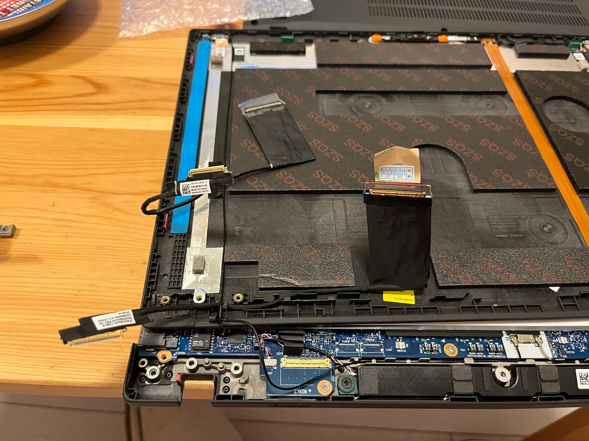
The LCD cable arrived after about two weeks. I had to carefully unplug the cable and unscrew the hinges from the laptop base, but it was all in all pretty easy to get the new cable routed in. The new panel came with new adhesive strips, complete with pull-tabs, so I set them down onto the designated spot in the LCD lid. Here's a shot of the new LCD cable routed, with the old one in the background, and the adhesive strips installed (with blue protective tape).
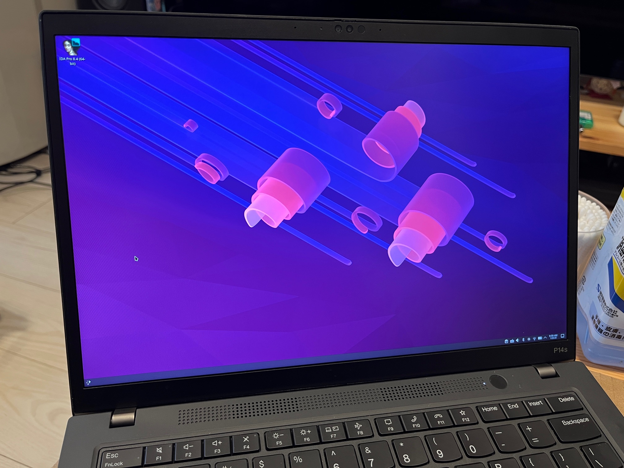
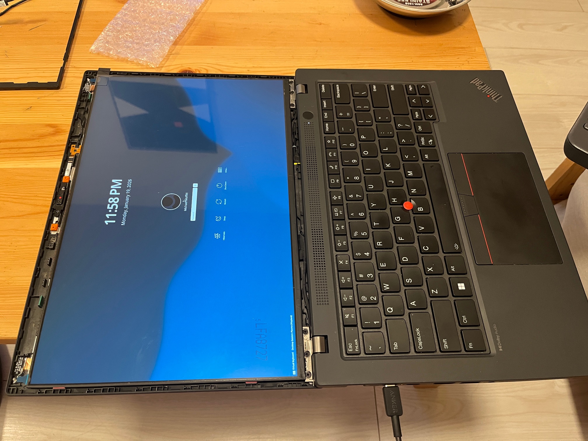
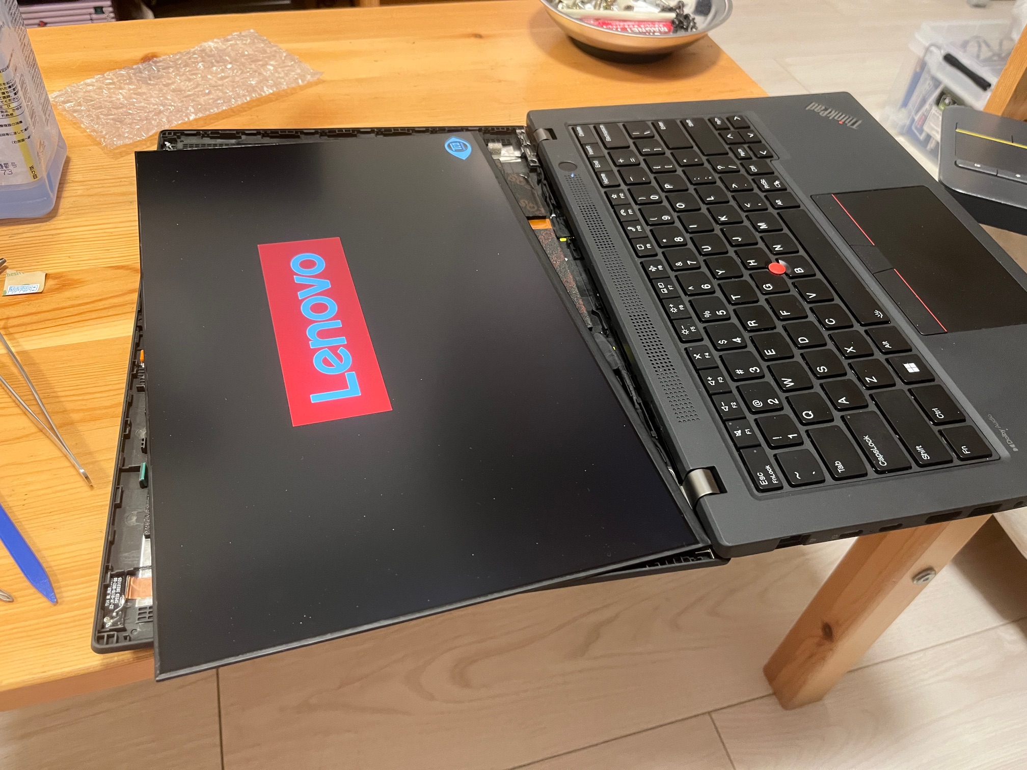
I completed the routing of the LCD cable through the hinge assembly and reinstalled it on the laptop base. With the new LCD lying on top of the lid, I hooked it all up and gave it a try. After a long initial boot (maybe it retrained its RAM for some reason?) the screen finally came up, and everything was working great. On top of that, the panel is bright and colorful! It's shiny in this picture as the shiny protective plastic is still installed, but it is in fact matte as I expected.
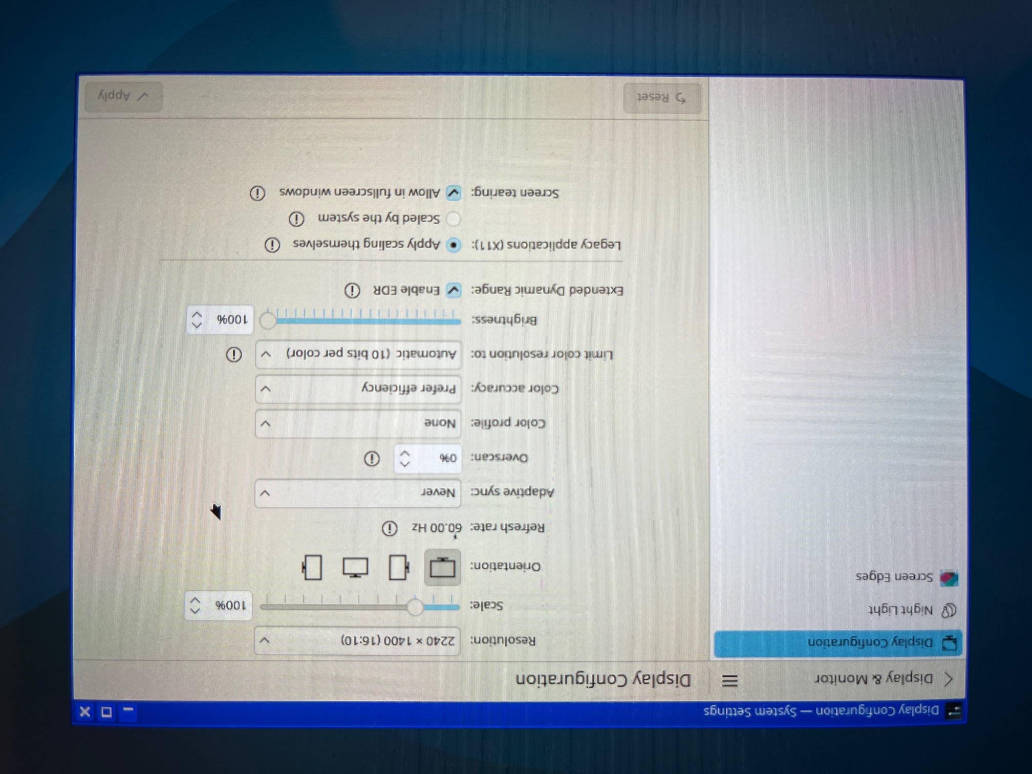
The display specifications also matched my expectations.
All seemed well, so I thought I'd just allow the adhesive strips to do their job, reinstall the bezels, and be done with it. After doing that, though, I couldn't help but notice the bezel didn't really sit right on the left and right sides. The LCD was somehow bowed outwards, like the original Trinitrons!
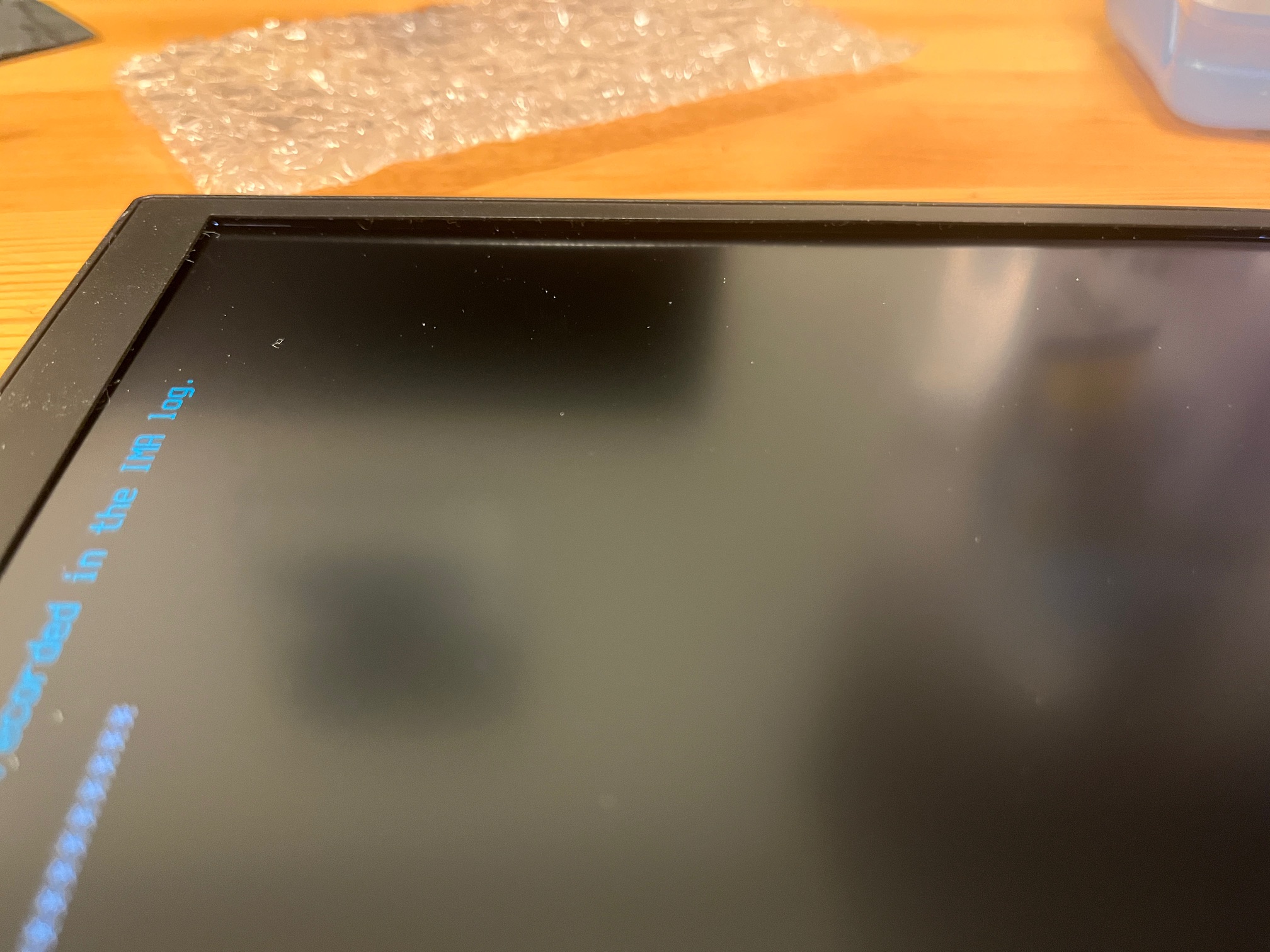
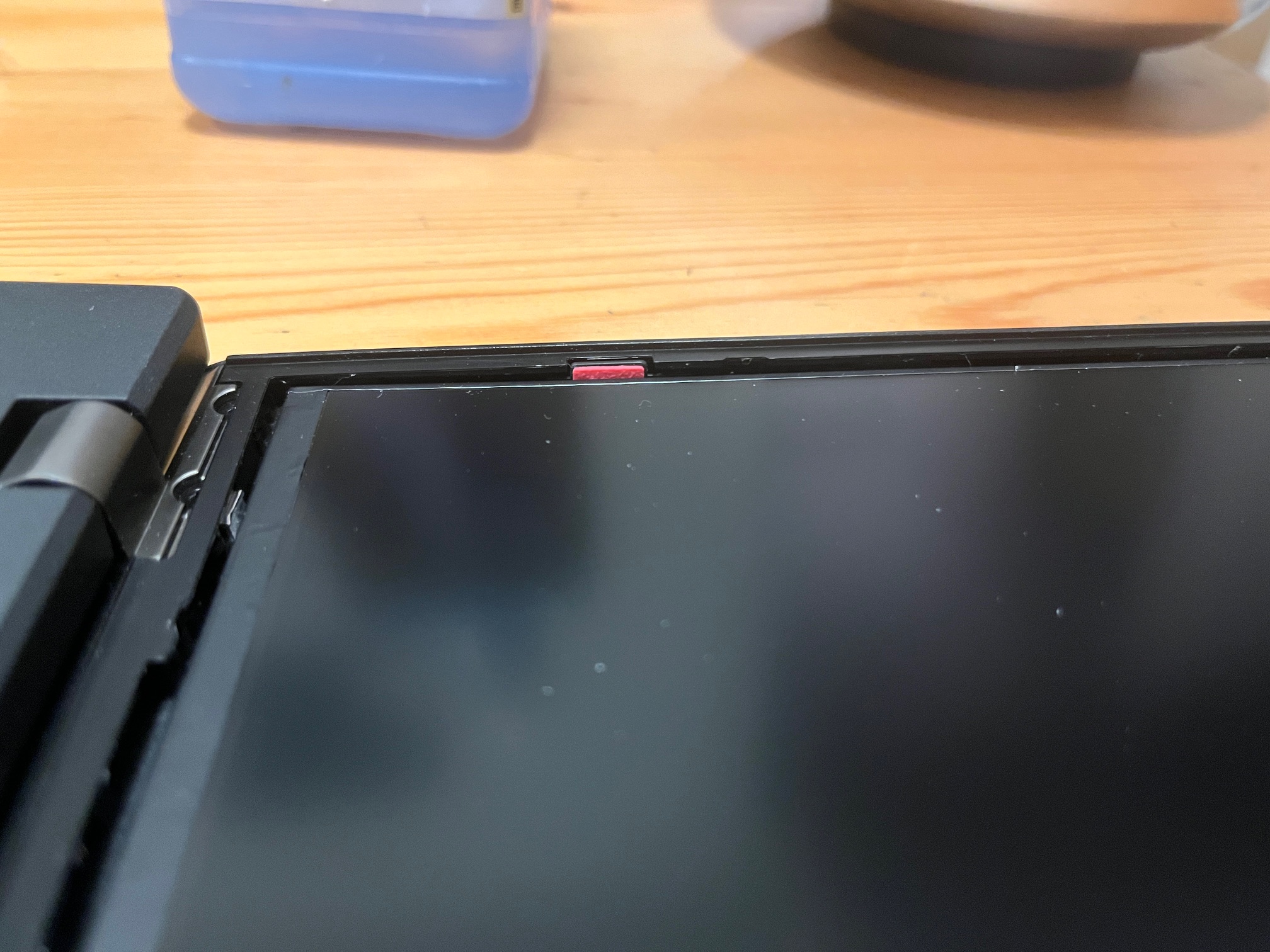
The bezel came off once more, and sure enough, the side looks inset somehow. You can see how the panel is quite below the sub-bezel and that red guide bumper, where it should be about level.
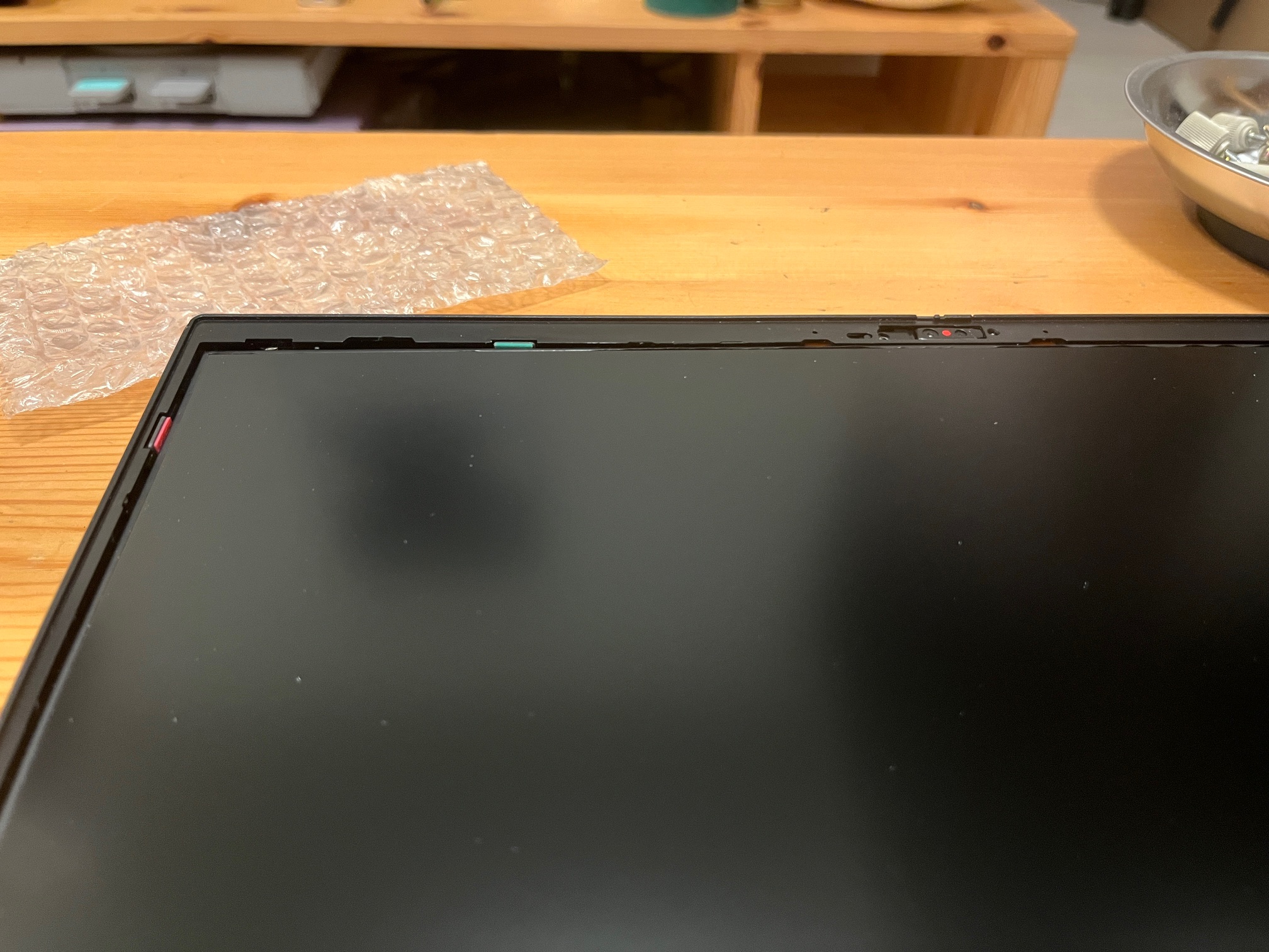
Looking at the top, it's pretty okay, but the side bowing is very obvious in this shot.
As there's nothing else at play, it must be the adhesive pulling the panel back, and all the foam acting as a fulcrum.
A flexed LCD is bad news so I wanted to get it out as soon as possible. I didn't want to repeat my mistakes from before, so I carefully used the pull tabs on the adhesive strips and successfully removed the panel without any damage.
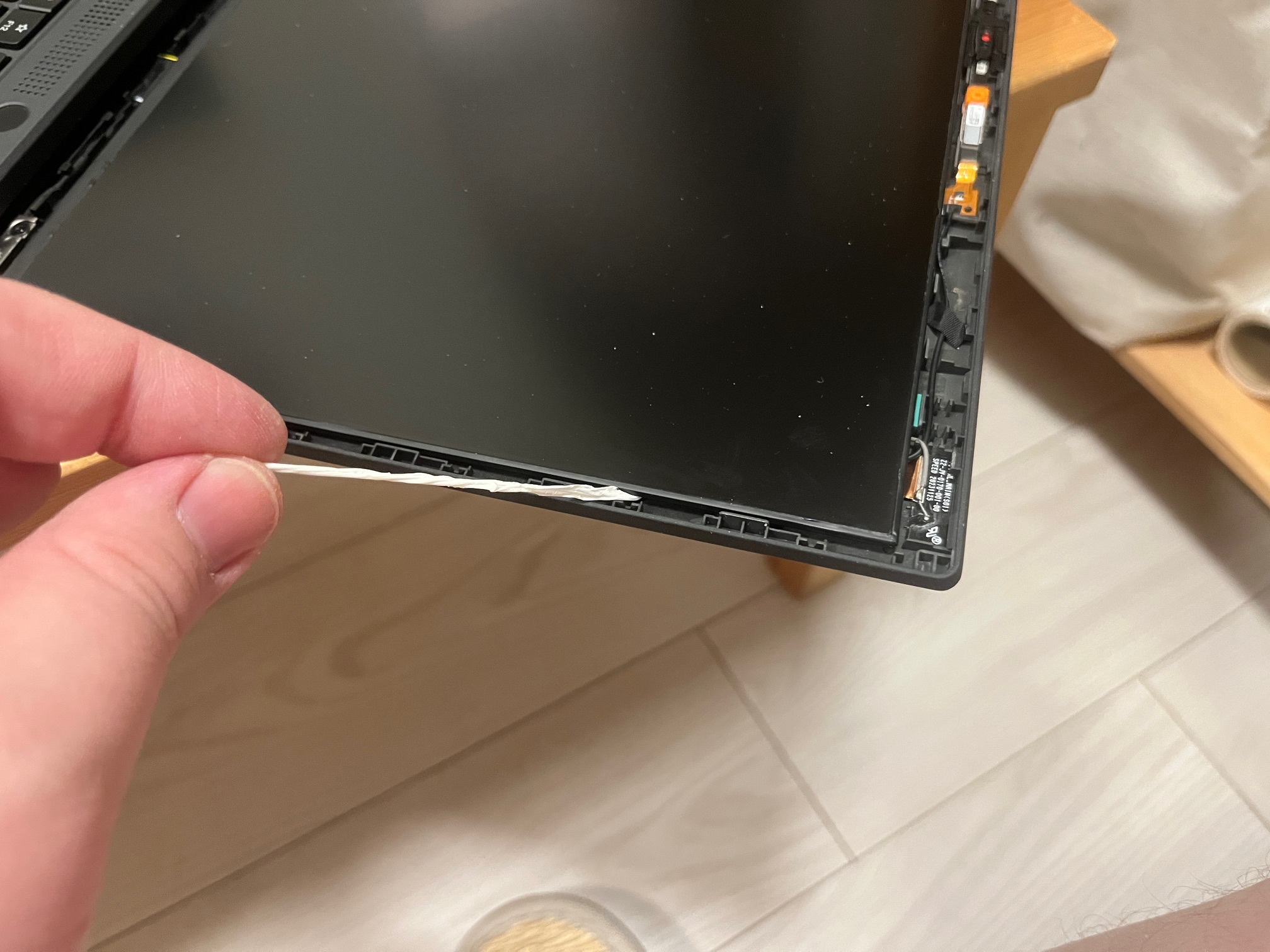
Just making sure it's still okay...
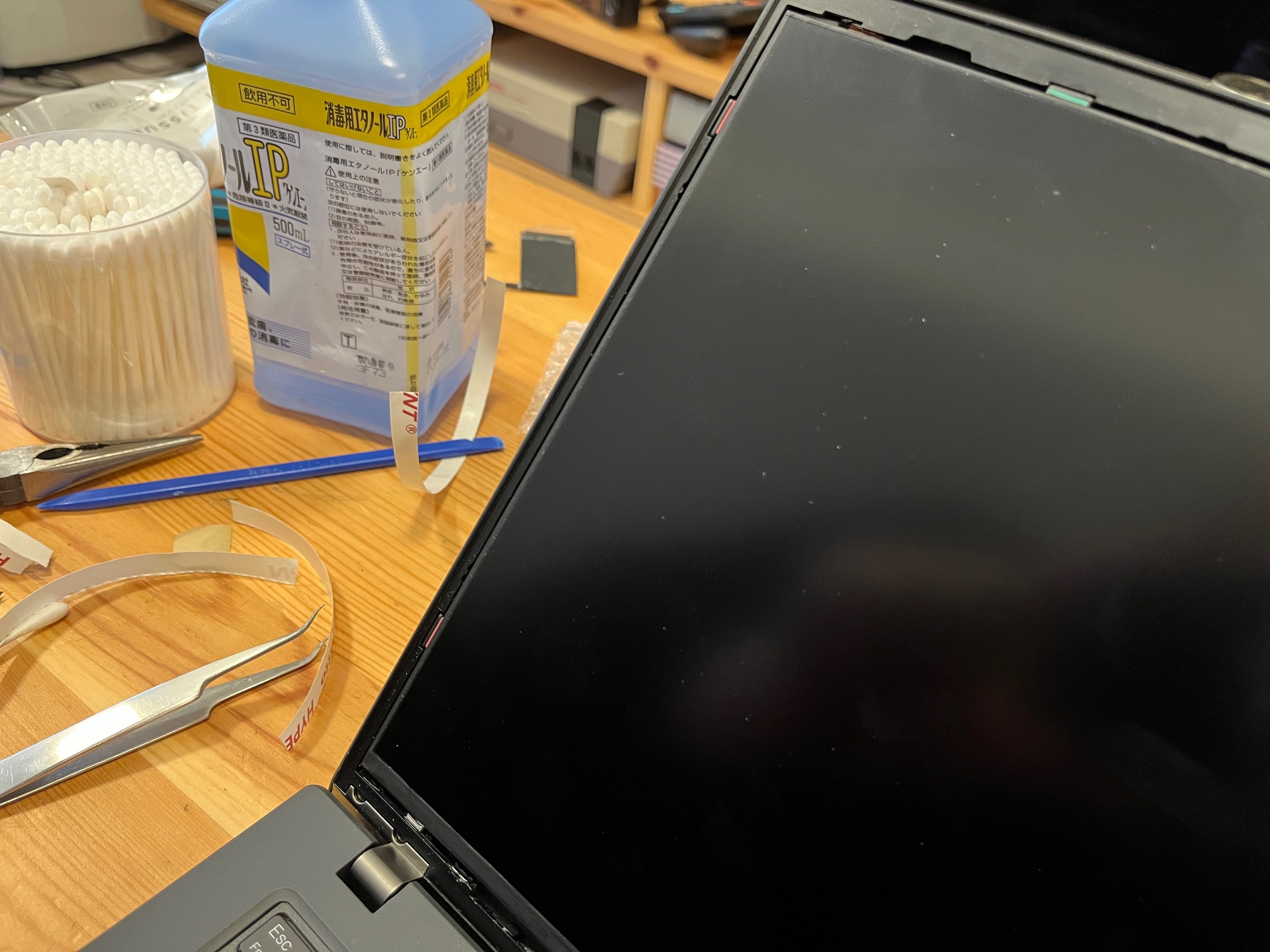
Operating under the theory that my adhesive strips were too thin for this panel/lid combo, I grabbed some double-sided tape I had on hand, "Nitto HYPERJOINT", and cut long strips to approximate the strips from before. I cut the strips longways and then double-layered them, to increase the thickness. I placed the resulting new strip in the lid, but kept the protective tape on so it wouldn't actually adhere yet.
With my new hand-made strips, the LCD panel seemed to sit in place a lot better than before.
I released the adhesion and placed the LCD panel for the final time, hopefully. With the bezel installed, it looks great, and shows no fitment issues. I think the story is finally over.