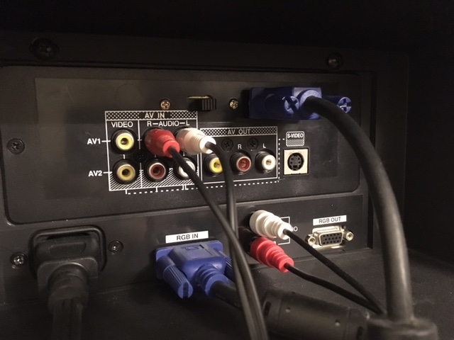
The NetTV rules as a large CRT monitor. It has a VGA port intended for computers! It can support 480p up to 768p through the VGA input. You can use a Dreamcast at 640x480 progressive scan. Modern consoles can be connected without too much trouble, and hooking a PC up and watching a movie actually looks quite good.
It also has traditional composite and s-video inputs. The best part is that the composite and s-video ports have the TV swithing scan rates down to 15KHz. That means they can do native 240p and 480i, without a line doubler or scaler!
This TV can be modified to accept low-res 240p / 480i RGB signals as well, though not through the same VGA port.
You might expect that a TV like this would naturally accept RGB at 240p. Sadly, giving the VGA port anything below 480 lines results in it just going into standby. The VGA port acts like a common VGA PC monitor. Even seperate H/V sync didn't make it happy.
I had the opportunity to get two of these NetTVs from Weirdstuff Warehouse, in the SF Bay Area. Given the size of the tube it was already appealing, but seeing the various inputs made it too good to pass up. One went to a friend, and I kept the other.
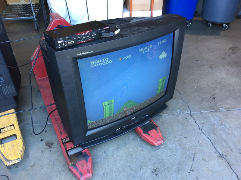
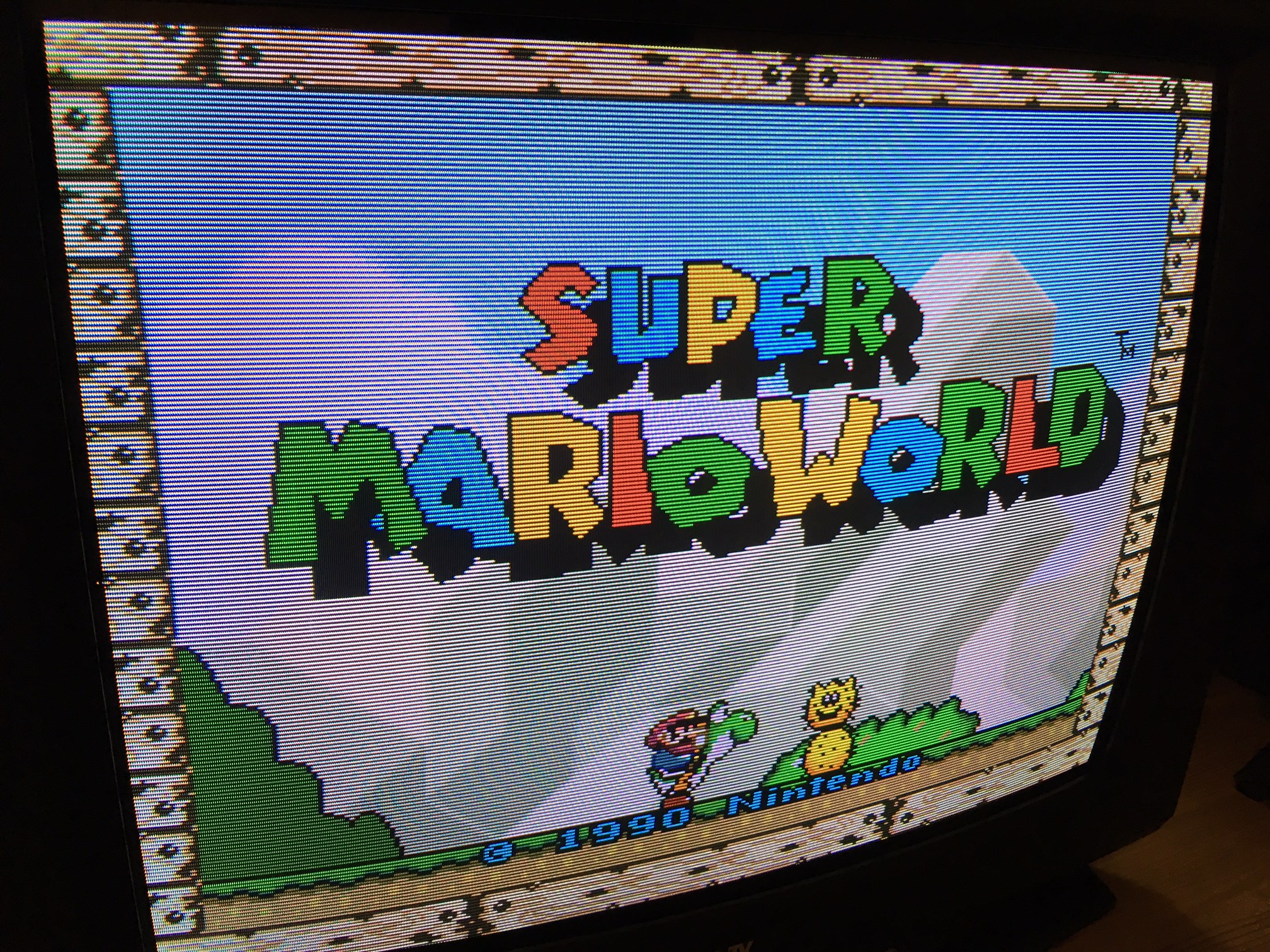
On site I gave it a test, and it was clear that 15KHz RGB didn't work through the VGA port, but I brought an XRGB3 to act as a line doubler so I could still generally try the set. Feeding line-doubled RGB to the scaler gives us a working 480p signal, which the TV accepted without any issues. The resulting image looks great, though the edges are a little too rectangular for my taste when I know this set has juicy native 15KHz rattling around inside it.
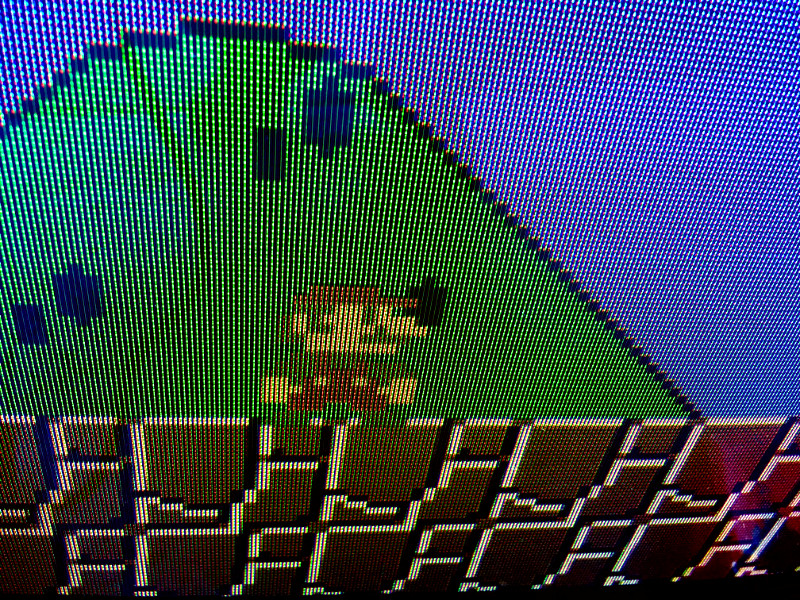
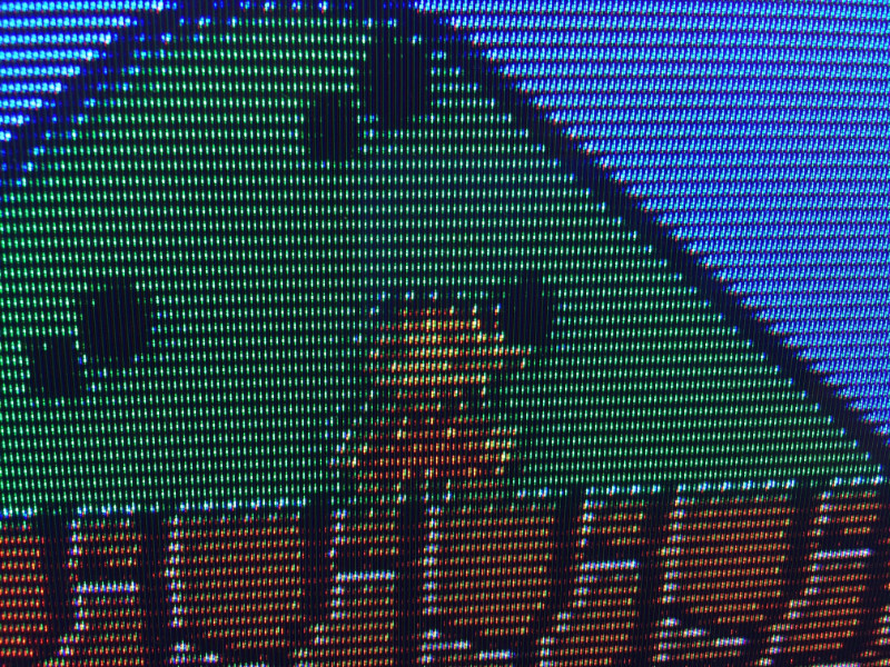
Of note is that the composite video inputs look abysmal, easily the worst composite I've seen on a set from the nineties.
Like many TVs, this one has an OSD. I figured it would be worth trying to inject RGB into the jungle IC when the TV is in 15Khz mode.
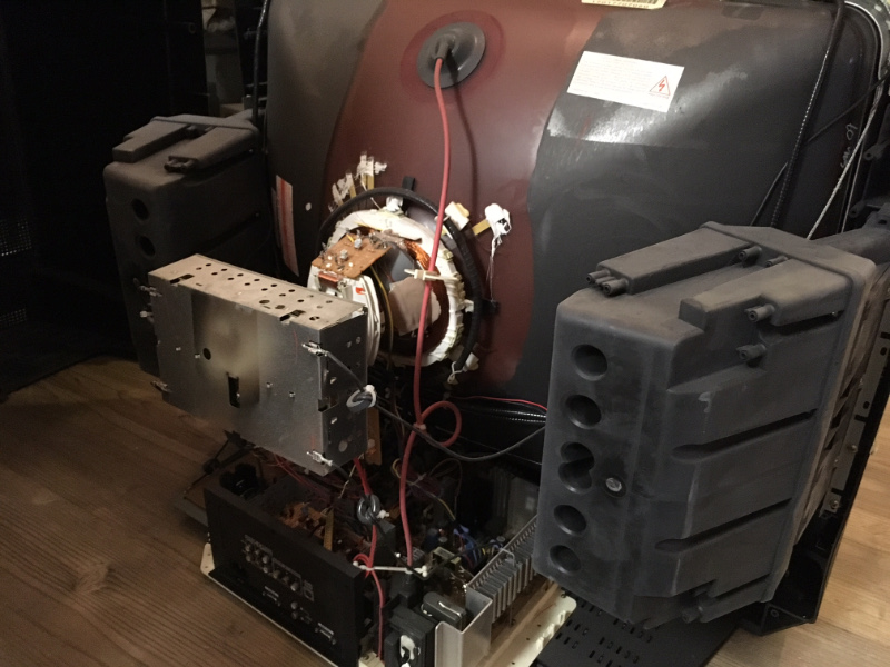
I cracked the TV open (with an absurd 18" screwdriver) and found that it wasn't dusty or grimy inside. I don't think this particular set saw a lot of use.
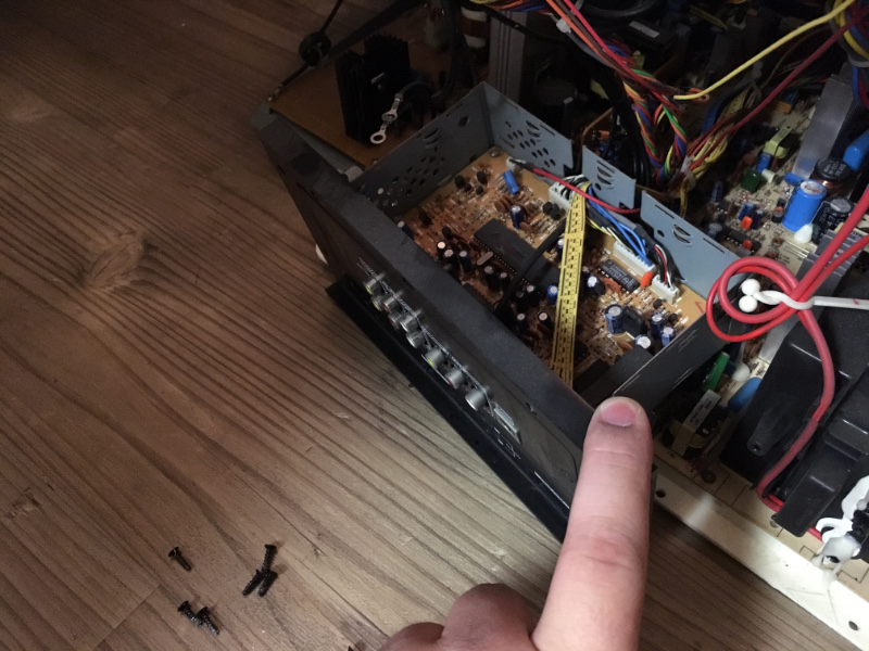
Towards the bottom, near the inputs, is a daughterboard right behind the low-res inputs. On it is a Phillips TB1227BN jungle IC. Great news: this jungle not only has an RGB input for the OSD, but it actually has a second unused RGB input, which is intended for closed-caption decoder outputs.
I pulled the daughterboard and brought it to the workbench. I did not have to touch the main chassis of the monitor at all as it was not necessary. I traced out the pins for the unused RGB2 input. The blanking line, YS2, was pulled low through a high-value resistor. The RGB2 input lines had all the termination necessary for a closed-caption board, and they run up to a a header in the corner.
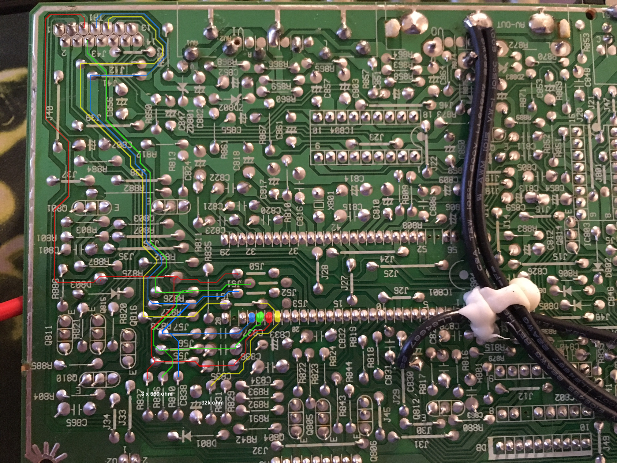
The board terminates the RGB inputs with 680 ohm resistors. I replaced these with 75 ohm resistors. I also tied YS2 high through a low-value resistor (75 ohms was fine) and attached this to a switch to let me use the composite inputs if I need them. I wired a port, bringing RGB to the resistors I had added for termination. I ran sync to the Composite 1 input through a 680 ohm resistor, as it is 75-ohm terminated and I wanted to reduce the current sunk from a TTL sync source.
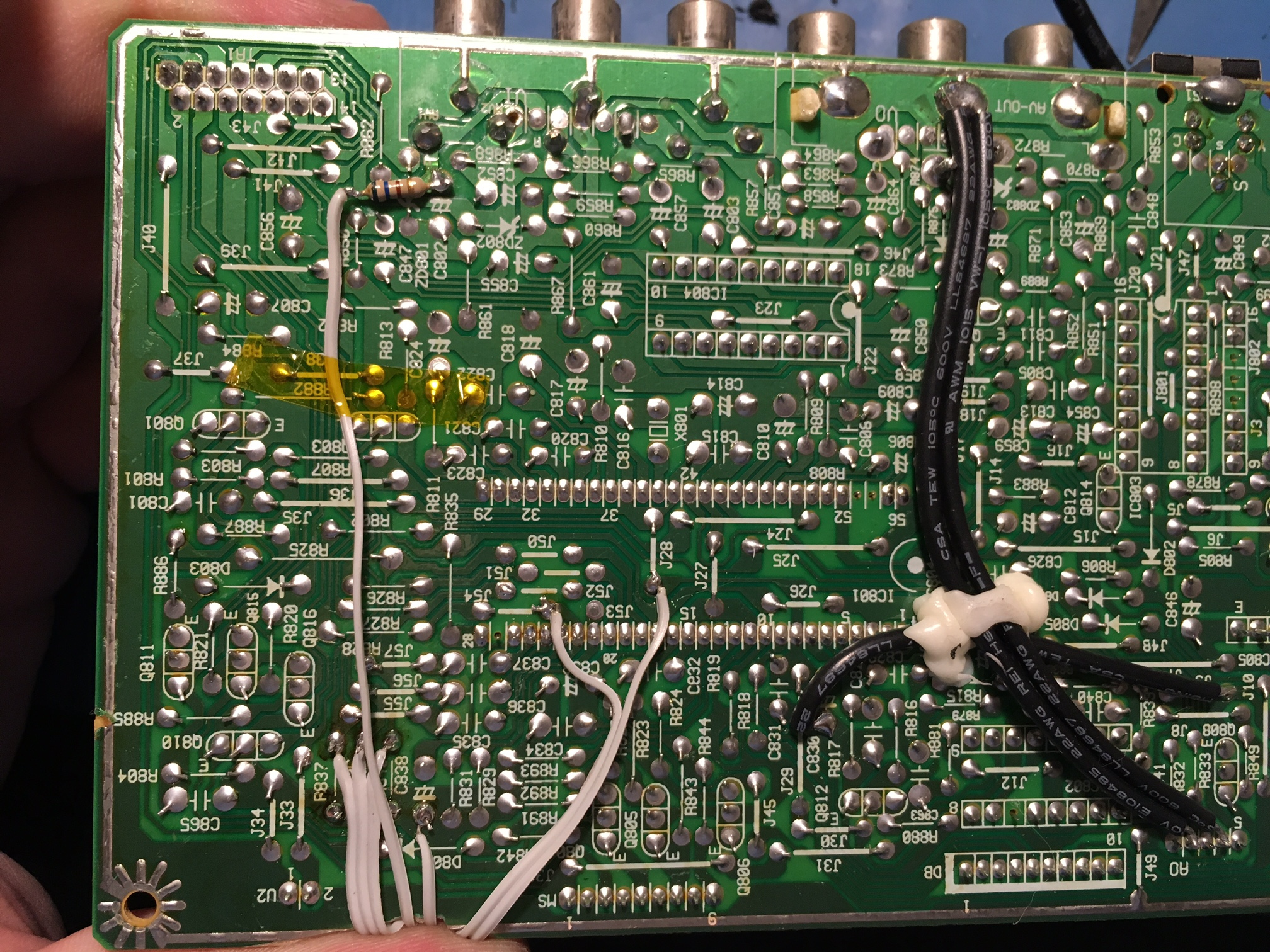
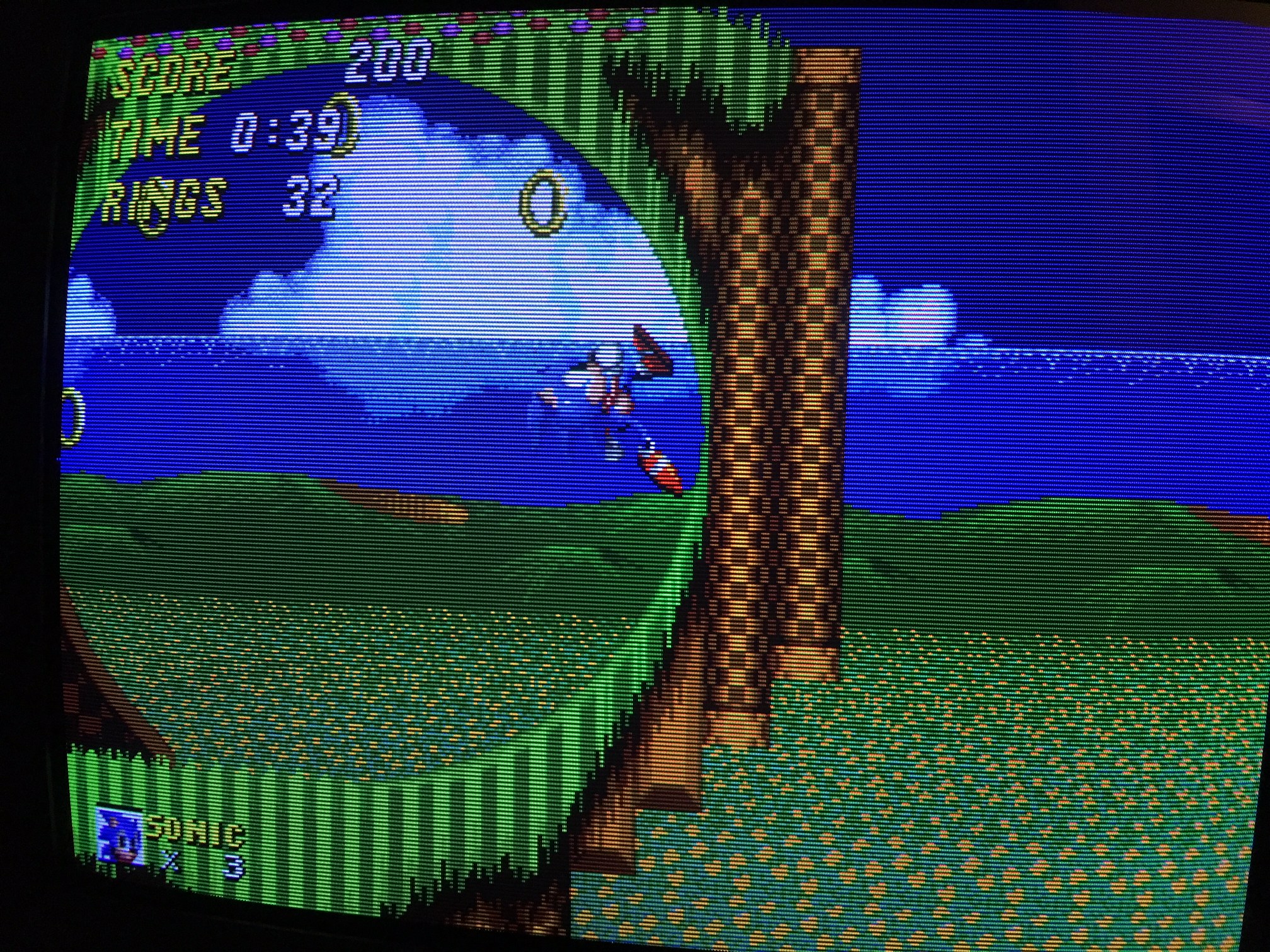
After all that, it worked on the first try (well, almost - I did the 75-ohm RGB termination change after having tried it as-is first). All I had to do was mount the port to the back alongside my switch, and I was done.
An extra nice feature of this RGB hack is that the OSD works on top of the RGB video without any extra work. If I was using SCART, I could use the SCART port's +5V signal to trigger YS2 to force blanking, which would make the TV automatically switch to RGB when given a signal and otherwise act completely normal. I don't run SCART, though, and my video cables do not supply power.
Forgive my handiwork here as I am not great at using the dremel (though the real problem is that I don't have the correct cutting bits for this!)