Important Warning!
I've been poking around the insides of high-voltage electronics like CRT monitors since I was a small child. Even then I was pretty aware of the dangerous implications and what is safe to touch versus what is not. Opening up an old television like this can be very dangerous if necessary precautions are not taken, and you are doing so at your own risk. Be sure plenty of research is done beforehand so you know what you're doing, and work with a friend if you've never done something like this before. This is meant to be informative, but it isn't a guide, so if you are going to attempt something similar then please be careful and do your own research prior!
Anyway, on with business.
 A long time ago, I did a pretty simple modification to a standard US television, where I fed RGB signals straight to the drive transistors on the CRT's neck board. This worked, but it required calibrating the G2 / "Screen" control voltage for each source, and the contrast was poor as it was designed around receiving 0 - ~4V instead of the 0 - 0.7V it was getting. It was a ghetto job, but it was pretty decent looking for what it was:
Now, three years later, I have a pretty beefy 32" CRT behemoth. It is the same standard resolution 15KHz type as just about every other real old-school CRT, but huge! Natively, it accepts NTSC broadcast, Composite, S-video, and YPbPr component video. Now, I run all of my systems in native RGB, so this leaves the "normal" option of converting the RGB to any of those formats. With YPbPr, it has the potential to look decent, but conversions can add compatibility issues, interference, and degradation, not to mention the price in getting an encoder. I've messed around trying to encode my own YPbPr, but it didn't turn out too well. Of course, this is my fault, and not that of the format itself.
The solution of encoding isn't really the solution I wanted. No, I want to pass it straight RGB! The true solution here lies in the way the TV's microcontroller works. It is responsible for digitally controlling settings like channel selection, picture adjustments, demodulating the input signals, volume control, sound redirection, user input, and most importantly the on-screen menu. This on-screen display (here on called OSD) is the part that will be useful to me. Since the CRT itself is driven by separate, amplified RGB lines, that means somewhere down the line there is RGB being mixed inside there (though you get the occasional TV that operates entirely in the YUV colorspace until the end, and even then some actually send THAT to the neck board!)
In order to overlay something like a menu over the normal content, two signals are mixed. Basically, as the beam scans left-to-right, it normally varies its intensity in order to render the image raster. If a menu is supposed to be popped up over the normal image, then when the beam is scanning that region of the image, the microcontroller will send the data for the menu instead of the TV image that is "behind" it. With this, it is superimposed over the original content. The blanking signal is a digital signal that tells it when it's time to display the OSD data instead of the normal one. This is not unlike how old arcade or console hardware would render backdrops and sprites over one another.
Now, with that little bit of thought out of the way I am left banking on the fact that this OSD signal is output as an RGB signal. One detail I left out is that the microcontroller often doesn't do this superimposition of video signals - that multiplexing is often handled elsewhere, and it was in the case of my TV. A little bit of sleuthing around and I found an old scan of the Japanese copy of the datasheet for a microcontroller that was very similar to this one - the pin count matched, and the part number was only off a little. It didn't say anything about RGB, OSD, or anything like that, but there were three pins marked as outputs with analogue capabilities. Analogue, you say... that's a good sign, since sometimes these OSD signals are digital only.
I snipped three jumpers across where capacitors could have been populated, which came from those three mystery pins. I then took my RGB signal and spliced it in there. By the way, I'm using the Composite Video input to give the TV sync data. As far as the TV knows, it's still just showing a normal signal, and this means the horizontal and vertical hold circuitry is working as it always did. The OSD is genlocked to the signal coming in.
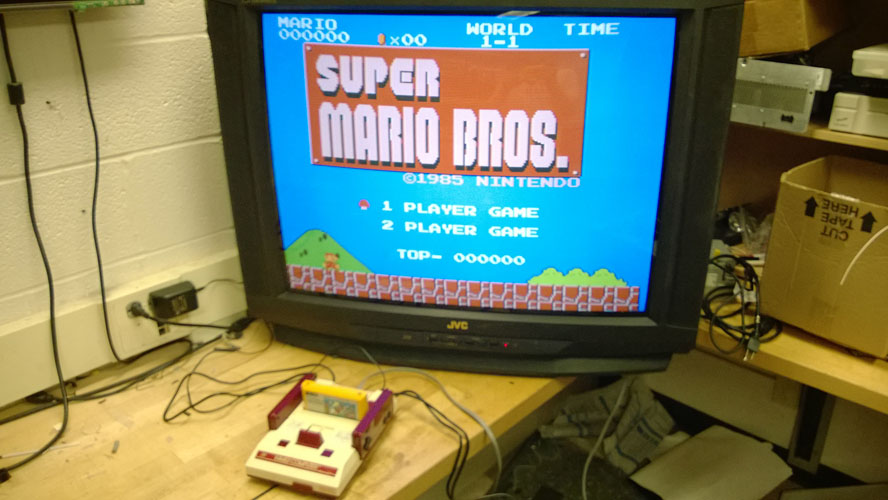
For those who aren't familiar (shame on you!) this is what the Super Mario Bros title screen looks like:
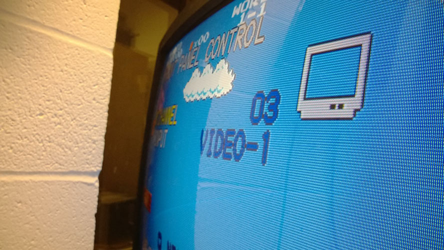
 Aaaaaaaaaaand here's the first thing I got, showing Super Mario Brothers on an RGB Famicom:
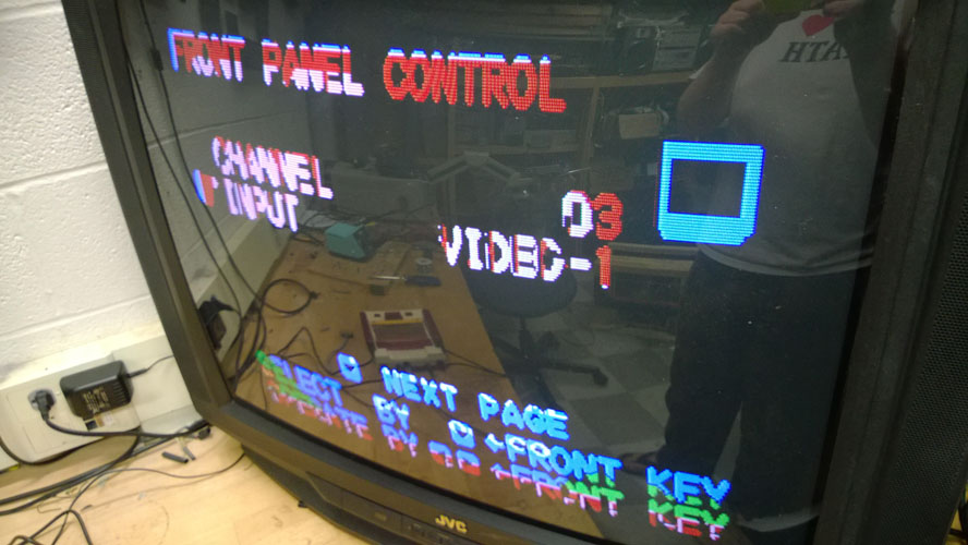 Sweet! I want it to fill the screen, though, it's hard to play through this little window of text, even though I got pretty far this way. This involved some trial and error, but I found the pin that outputs normally to the blanking circuit, and tied it to 5V to keep it blanking always. This means the whole screen is RGB.
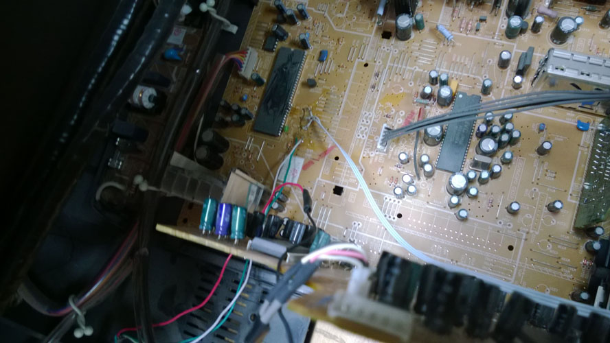 However, there are times when I may want to be able to see the menu, or use S-video or something. I put a switch up top that sends either 5V or the original blanking signal to let me choose. I'm not switching the RGB lines, though, so the menu shows up as black (or really whatever RGB signal is active at the time). It's usable enough for now.
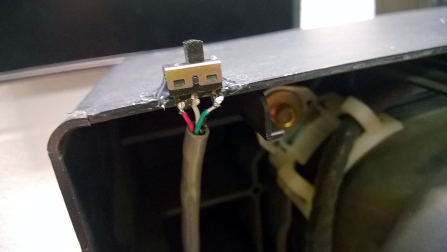 I mounted an HDB-15 port (that's VGA!) to the back to feed it RGB. I use this for all of my RGB stuff since the cables are well shielded and easy to get for cheap. I use a VGA switchbox for source selection. For the curious, I wire RGB to pins 1, 2, and 3, ground pins 4-8, and put the composite sync signal on pin 13 (normally H-Sync). This configuration has worked 100% of the time for every digital projector I've used. For some reason, while basically no HDTVs will take 15KHz RGB, every projector I've tried takes it through VGA without any complaints, often identifying it as SCART, which is Europe's native RGB connection standard on most TVs.
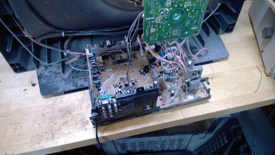 Guess what this VGA port was snipped off of! I terminated each connection to ground with 75 ohm resistors on R, G, and B, as just about every proper RGB signal expects 75 ohm termination.
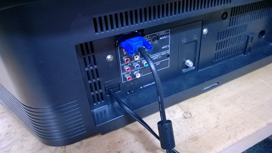 For the last step, the VGA pin 13 was wired to the YPbPr's Y input. I could use composite video or s-video, but those signals are shifted to the left by the TV to counteract the slight line delay introduced from the demodulation and comb filter used to clean up the signal. The YPbPr doesn't do this, so the image is better centered this way. I may try to find a remote for this TV and get into the service menu to fix up the geometry once and for all...
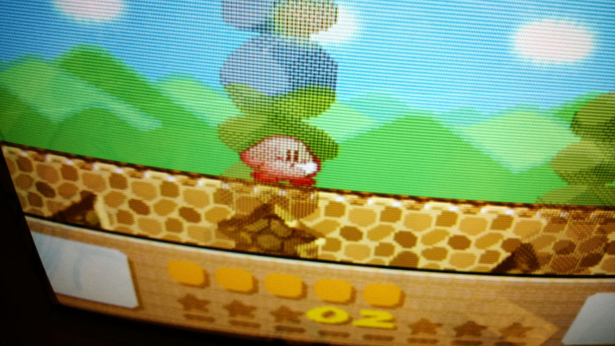 Anyway, it looks great! It works with everything I've used on it, with no adjustments needed per-console. That list is RGB NES/Famicom, SNES/SFC, Sega Genesis/MD, Sega Saturn, Neo-Geo MVS, various JAMMA arcade boards, and Dreamcast.
Back to main index